The article systematically presents the stages of research conducted on the transformation of a standard passenger carriage into a specialized technical-purpose vehicle, intended for operation within both passenger and freight train formations. The performance test results of the prototype dynamometric unit under applied load conditions indicate that the redesigned structure meets established durability standards. Moreover, the stress-strain behavior of the structural components remains within the allowable limits.
In order to establish an integrated railway system across the territory, numerous large-scale infrastructure initiatives are currently underway. These include the expansion and modernization of railway lines, as well as the upgrading of the fleet with locomotives and wagons that possess enhanced technical and economic efficiency [1]. Given the current deficit in rolling stock and the limited capacity reserves on the most intensively utilized segments of the rail network, increasing freight turnover necessitates exploring innovative development strategies. These involve both the modernization of existing lines and the construction of new ones, along with the adoption of advanced rolling stock technologies [1–4].
Hence, the creation and enhancement of special-purpose rolling stock designs have become key areas of focus. Such developments are vital not only for maintaining traffic safety, particularly in mountainous terrain, but also for optimizing locomotive traction, evaluating longitudinal dynamic forces between railcars and locomotives, and ensuring efficient train operations.
The main objective of this research is to design a dynamometric railcar for technical-special applications, which, in terms of construction and performance, meets the required safety standards for integration into both freight and passenger trains.
In order to identify the key issues, assess the current condition, and outline promising directions for the development of the fleet, the structural features of both local and international passenger wagons, as well as special-purpose technical wagons, have been comprehensively analyzed. Despite the diversity of existing rolling stock configurations and the numerous theoretical and practical efforts aimed at their enhancement, there remains a noticeable lack of attention in scientific literature regarding the design and modernization of dynamometric wagons tailored for special-technical use, especially those adapted from passenger models intended for operation within freight convoys.
As a result of the conducted analysis, a particular passenger wagon structure was chosen as the basis for further theoretical modeling and experimental validation. The goal is to adapt and optimize this design into a special-purpose dynamometric unit capable of functioning effectively in both passenger and cargo transport settings.
To analyze the stress and load distribution within the passenger car body structure, a 3D digital model of the body was created using the SolidWorks 2024 software suite. This modeling process aimed to support the modernization and transformation of the passenger car into a dynamometric vehicle designed for special technical applications (see Figure 1).
|
|
|
|
(a) |
(b) |
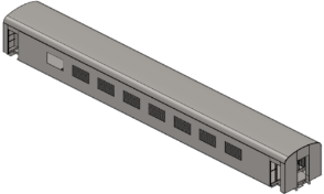
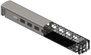
Fig. 1. a) General view of the spatial model of the passenger wagon body structure; b) metal structure of the spatial model of the passenger wagon
To carry out theoretical research, the wagon body model developed in the SolidWorks 2022 software package was imported into the ANSYS Workbench 2022 software, on the basis of which an updated finite element model of the passenger wagon body was developed (figure 2), which allows taking into account the features of the variants of the design decisions taken in the calculations. Namely, changing the geometric dimensions of the body and frame elements (center sill, lateral longitudinal and transverse beams, braces and other elements), which will allow us to reasonably choose the optimal thicknesses of the reinforcing elements of the passenger wagon depending on the operating conditions.
To determine the loading capacity of the wagon body structure, stress distribution in the body elements and reinforcement zones, several transverse measuring sections with virtual measurement points installed on them were provided in the design model of the body to obtain individual stress values at each of the points.
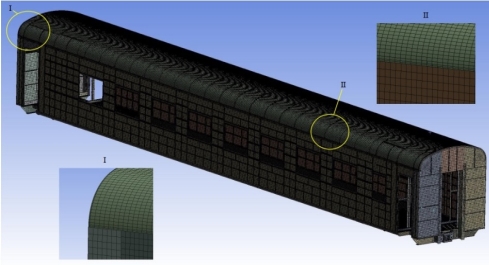
Fig. 2. Computed finite element simulation of a passenger coach structure
As a result of structural strength assessments conducted using the Finite Element Method (FEM) in ANSYS Workbench 2021, in accordance with the guidelines outlined in references [2–4], the maximum stress values at virtual control points were determined under the action of longitudinal loads applied to the front and rear stops of the wagon’s auto-coupling system. Figure 3 illustrates the stress distribution patterns based on the von Mises criterion for the wagon body components in the initial loading scenario.
|
(a) |
|
|
(b) |
|
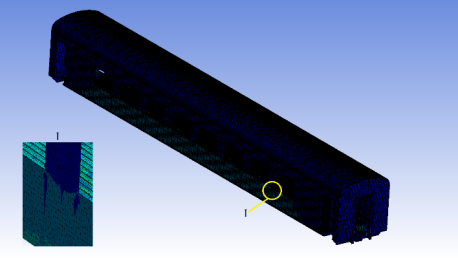
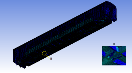
Fig. 3. a) Top view of the stress distribution patterns in the structural components of the wagon body under Design Mode I (characterized by central interaction of automatic couplers and a compressive load of 3.4 MN); b) Bottom view of the stress distribution patterns in the structural components of the wagon body under Design Mode I (characterized by central interaction of automatic couplers and a compressive load of 3.4 MN)
The obtained relationships of the maximum equivalent stresses occurring in the structural elements have made it possible to conclude that the stress variations in the side walls and roof components under increasing longitudinal loads are minimal, and their magnitudes remain within the allowable limits. However, the stresses observed in certain sections of the wagon frame exceed the permissible thresholds. Therefore, in order to identify the areas requiring reinforcement, further investigations were conducted specifically on the wagon frame.
Based on the conducted analysis of the wagon frame loading under the influence of longitudinal forces—ranging from 1 to 3.41 MN, depending on the operational mode and applied to the front and rear stops of the automatic coupling system—the peak stress values at each virtual measurement point were determined [3–5]. Figure 4 illustrates the stress distribution patterns in the wagon frame elements, according to the Mises stress theory, under conditions of central interaction between the automatic couplers.
|
(a) |
|
|
(b) |
|
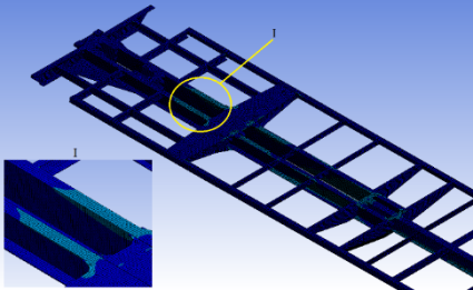
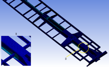
Fig. 4. a) top view of stress distribution fields in the elements of the carriage frame at the I design mode (compression force of 3.41 MN); b) bottom view of stress distribution fields in the elements of the carriage frame at the I design mode (compression force of 3.41 MN)
Analysis of the research outcomes indicates that the peak stress experienced in the frame components—primarily in the center sill—reaches 521.91 MPa. This value surpasses the allowable stress limit of 275.4 MPa according to the first design condition. Consequently, in order to ensure the reliable operation of the modified wagon within freight trains subject to increased longitudinal forces, it is essential to strengthen the most heavily loaded elements of the frame of passenger wagon. This reinforcement aims to enhance the structural integrity of the metal framework for its conversion into a dynamometric wagon designed for special technical applications.
Based on the conducted studies, it was established that to meet the prescribed standards, the center sill located in the central section of the frame of the specialized dynamometric wagon—constructed using I-beam No. 30—must be reinforced on both sides along its full length. This reinforcement should consist of 8 mm thick steel plates that connect the upper and lower flanges of the I-beam on both sides of the web, as illustrated in Figure 5.
|
(a) |
|
|
((b) |
|
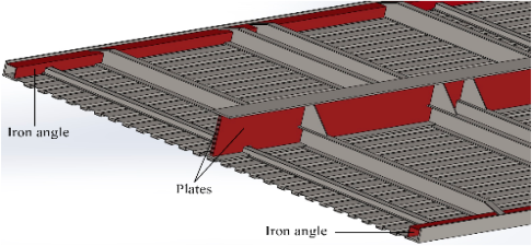
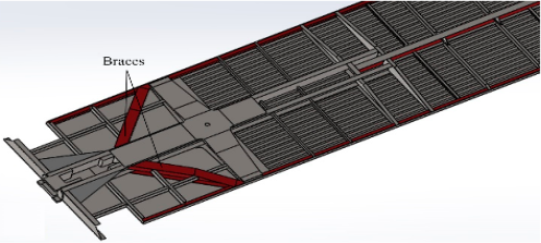
Fig. 5. a) Wagon frame with reinforcing iron angle and plates; b) Wagon frame with reinforcing braces
To minimize stress on the center sill in the cantilevered section of the frame, it is essential to install special reinforcing beams (braces) made from I-beams. These braces should be anchored at one end to the center sill and at the other end to the side longitudinal beams of the frame. This configuration enables the redistribution of a portion of the longitudinal loads—transmitted through the automatic coupling device stops—to each of the side longitudinal frame beams. At the points where the braces are attached to the structural ties, a narrowing should be provided without altering the cross-sectional profile.
Furthermore, the side longitudinal frame beams, located between the door openings along the entire length, must be internally reinforced between the cross beams using equal-angle steel sections measuring 75×75×5 mm.
As a result of comprehensive structural and computational investigations utilizing the finite element method (FEM), an optimized and reinforced design of the passenger car body has been developed to facilitate its conversion into a dynamometric wagon for specialized technical applications, including dynamic load measurement and performance monitoring in mixed passenger and freight train operations.
The proposed design introduces a significant improvement in structural integrity and operational reliability. A key enhancement involves the replacement of the standard center sill with a robust I-beam configuration. This I-beam is reinforced on both sides with high-strength steel plates, which effectively connect the upper and lower flanges, thereby increasing resistance to bending and torsional stresses under heavy load conditions.
Furthermore, to ensure additional lateral stability, equal-angle steel profiles are strategically welded to the inner surfaces of the side longitudinal beams, precisely between each pair of cross beams. This configuration enhances the frame's rigidity and contributes to a more uniform stress distribution across the entire structure. In the cantilevered end sections of the underframe, diagonal braces are integrated to connect the center sill to the side longitudinal beams. This advanced design not only meets all safety and regulatory standards but also ensures long-term serviceability and ease of maintenance, making it a viable solution for the modernization and reconfiguration of existing rolling stock for advanced instrumentation and testing purposes. Based on comprehensive theoretical and experimental studies, it has been established that the design of the newly developed special-purpose dynamometric wagon meets all strength and safety requirements. It is suitable for integration into both passenger and freight train compositions. The advanced structure of the wagon body, derived from an improved version of a standard passenger carriage, was successfully implemented at the Tashkent-based plant specializing in the manufacturing and refurbishment of passenger rolling stock during the construction of this specialized dynamometric wagon.
References:
- M. X. Rasulov et al. “Problems of increasing the competitiveness of domestic railway corridors” in Resource-saving technologies in railway transport, Scientific proceedings of the Republican Scientific and Technical Conference, 2013, pp. 14–17.
- R. V. Rahimov et al. “Commissioning of the freight wagons with increased axle loads is a guarantee of the further development of railways of the Republic of Uzbekistan” in E3S Web of Conferences, EDP Sciences, 2021, pp. 1–11.
- GOST 33788–2016, Freight and passenger cars. Methods of testing for strength and dynamic qualities. Standartinform, Moscow, 2016, 41 p.
- Yu.P. Boronenko et al. “Method of continuous registration of dynamic processes of interaction between rolling stock and railway track” in Advances in dynamics of vehicles on roads and tracks II, Proceedings of the 27th Symposium of the International Association of Vehicle System Dynamics, Lecture Notes in Mechanical Engineering, 2021, pp. 450–460.
- Yu.P. Boronenko et al. “Develop a new approach measuring the wheel/rail interaction loads” in Proceedings of the 2021 Joint Rail Conference, 2021, pp. 1–8.

